AVR-based cooling fan controller
For a while I have been working on getting my computer more silent and more performant and I have made some progress by getting the cooling fans (and a water pump) controller ready to be used.
I started the project somewhere around 2013. I had some background in programming PIC controllers but the better software toolset (avr-gcc!) made me try out AVR for this thing. I chose the Atmega88 controller which is old but popular and had enough IO features.
There were already quite many existing fan controller projects on the Internet but not single one of them had all the features I needed:
- Enabling/disabling fan power. Many fans, including all those that I got, keep turning even when PWM signal is set to 0.
- Pulse stretching. This makes it to possible to PWM-modulate devices that otherwise do not include built-in support for it. Pulse stretching sets full PWM (continuous power) during RPM measurement which guarantees proper reading.
- Simple feedback algorithm that can be updated without recompiling the firmware.
Hardware
The hardest part in the hardware design was allocating correct pins to suitable IO features. This task is hard because enabling some features on certain pins can disable others. The PWM signal generation, which uses built-in hardware support, needs proper selection of timers and also one timer had to be used for measuring RPM.
The circuit around the MCU is straightforward and contains some low-pass noise filters, protection resistors, and power switches for fans. The single-sided PCB was routed manually using the Eagle software and etched by using the tone-transfer method.
Firmware
The firmware is written in C. Most of the code deals with the device setup and RS-232 communication. All IO besides RPM measurement is set up using interrupts. The main loop circles through enabled fans and runs RPM measurement, adjusts PWM using the control tables and sensor input, and also sets error signal when a fan RPM reads 0.
Feedback algorithm
Initially I thought that I need something really complex, like an embedded mini-language interpreter. However, the actual solution turned out much simpler (but not Turing-complete!) thanks to the usage of decision tables. The feedback is in the form of a table:
| Min t. | Max t. | Fan 1 PWM | Fan 2 PWM | Fan 3 PWM | Fan 4 PWM |
|---|---|---|---|---|---|
| 0 | 40 | 0 | 0 | 0 | 0 |
| 50 | 255 | 128 | 128 | 0 | 0 |
This represents the following algorithm:
When the temperature is in range 0 to 40 °C
    then disable all fans.
When the temperature is above 50 °C
    then enable both 1st and 2nd fan with half PWM (255 is max).
When the temperature is in range 41 to 49 °C
    then do nothing.
The "do nothing" part allows to implement hysteresis in the control feedback which prevents the fans constantly turning on/off. The actual table rows also contain per-fan control bits whether to change the fan PWM at all. There is one table per sensor (two sensors) and maximum of 5 active rows per table. The rows can be queried and updated through the RS-232 interface.
PC client
The PC client can be used for debugging the device and for updating the control table lines. It is written in NodeJS and uses the serialport package to connect with the RS-232 port.
The source code (and more detailed description) for the firmware, pc client and hw design files is on GitHub under the MIT license.
Photo of 2 completed units (MCU not plugged in):
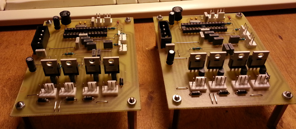
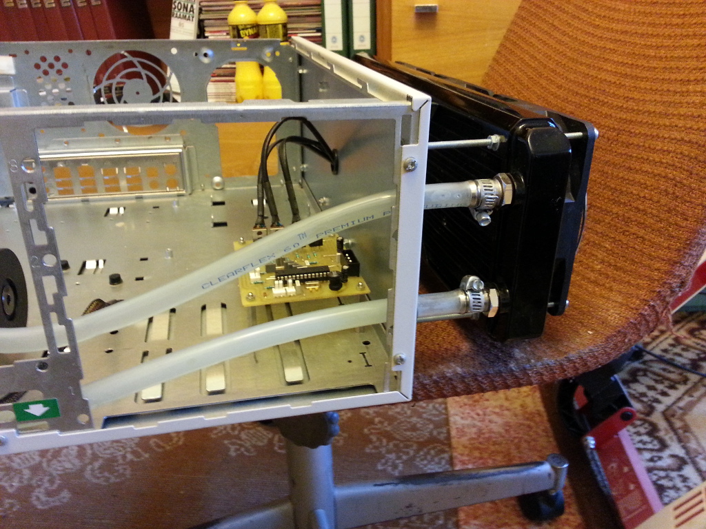
Photo of the installed unit: