Hello world from DXF
Last week I worked on a code to convert SVG to
DXF. SVG (Scalable Vector Graphics) is a vector graphics format supported by most browsers.
DXF (Drawing Exchange Format) is another vector format, mostly used by CAD applications. Our CAD editor at Scale Laser, a startup focusing on model
railroad builders, uses a SVG-based drawing editor in the browser but the software controlling the actual cutting hardware uses DXF. There were no
usable generic SVG to DXF converters available and we had to write our own. We only deal with SVG <path> elements and do not have
to support other SVG elements.
DXF is fairly well specified through a 270-line PDF file here. The low-level data serialization format feels ancient compared to more structured XML and JSON. Also, it is quite hard to put together a minimal DXF file which can be opened by the most programs claiming DXF compatibility or that can be opened with AutoCAD itself. AutoCAD is the original program to use the DXF format.
I have put together a minimal file by trial-and-error. I kept adding stuff until I got the file loading in AutoCAD. The file follows and I explain the parts of it.
Sections
A DXF file consists of sections. The most important section is ENTITIES that contains graphical objects. Another important section is
HEADER:
  0
SECTION
  2
HEADER
  9
$ACADVER
  1
AC1009
  0
ENDSEC
All sections are made up using group code-value pairs. A such pair is formatted like:
  <code>
<value>
The group code specifies either the type of the value (string, float, etc) or its semantic meaning (X coordinate) or both the type of the value and
the meaning. A section begins with the SECTION keyword and section's name. A section ends with the ENDSEC keyword.
I found it was necessary to specify the file/AutoCAD version in the header. Without it, some tools, including AutoCAD, would give errors upon opening the file. This is accomplished by two code-value pairs:
  9
$ACADVER
  1
AC1009
This corresponds to the versions R11 and R12.
Lines
After the header comes the actual content section ENTITIES. It contains a rectangle made up of 4 lines (snippet truncated to show a
single line only):
  0
SECTION
  2
ENTITIES
  0
LINE
  8
0
  62
8
  10
169.50
  20
42.33
  11
169.50
  21
94.19
...
  0
ENDSEC
  0
Graphical objects are specified one after another, without any further structure. A line starts with the LINE keyword and ends with the
start of another object or with the section end. The line object here has the following properties.
The layer index (group code 8, value 0). I was not able to make the file display on most viewers without it:
  8
0
The line color (group code 62, value 8 - gray). Nothing was visible in some viewers without setting it:
  62
8
After that come the start and end coordinates of the line (X1, Y1, X2, Y2 as 10, 20, 11, 21 respectively):
  10
169.50
  20
42.33
  11
169.50
  21
94.19
DXF coordinates have no units such as pixel, mm etc. Interpretetion of units seems to be implicit and application-specific. For example, our laser software assumes mm as the unit.
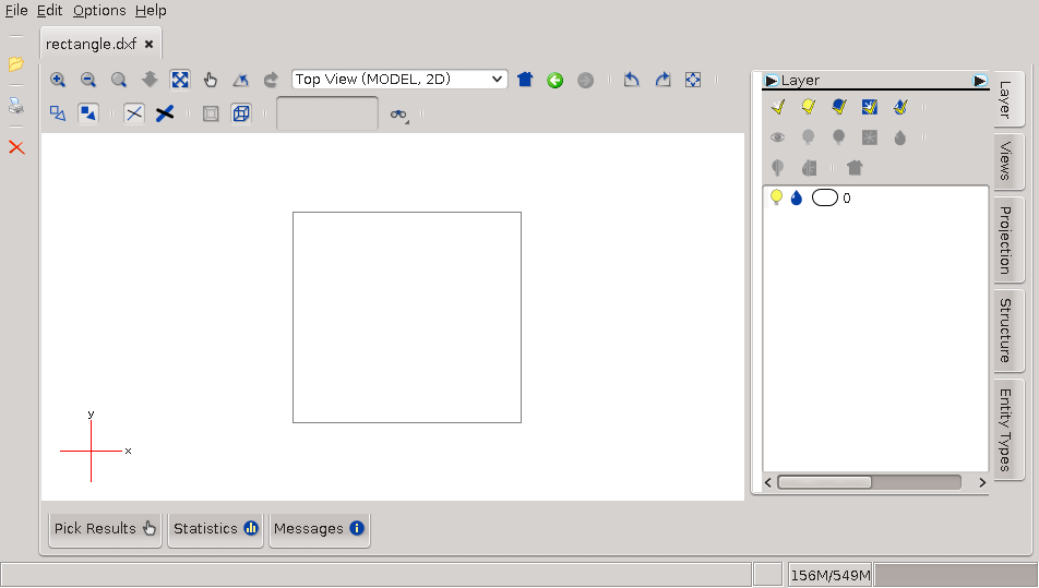
Rendering output
This is the rendering output in de-caff, a simple Java-based DXF viewer:
This is the rendering output in AutoCAD 2017:
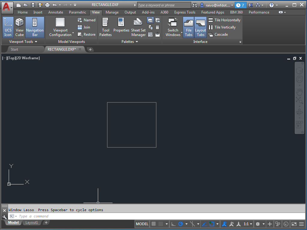
The full file containing the rectangle and the header section can be downloaded from here.