High power car amplifier
A while ago in the last summer I finished my last DIY hardware project: a car amplifier and a subwoofer. The car amplifier is a rather complex project if built from scratch as it includes a power inverter. A power inverter is much trickier to build compared to usual audio amplifier circuits.
Fortunately I had already built the inverter around 2005 when I was a bit more interested in electronics and hardware. It had been sitting unused although it worked well according to bench tests. I also had old amplifier modules so that the project was just about connecting them and mounting them in a suitable case.
Power inverter
The schematics of the power inverter was based on a schematics published on the Elliott Sound Products (ESP) site. The build instructions only contain schematics and some generic rules for working with switching power supplies. The original circuit has a big flaw that does not come out with bench testing and which I had to fix after testing the system in an actual car.
As there is was no physical layout specification or PCB drawings, I made my own. The circuit is divided into 3 subsystems: the input section, the conversion section and the output section.
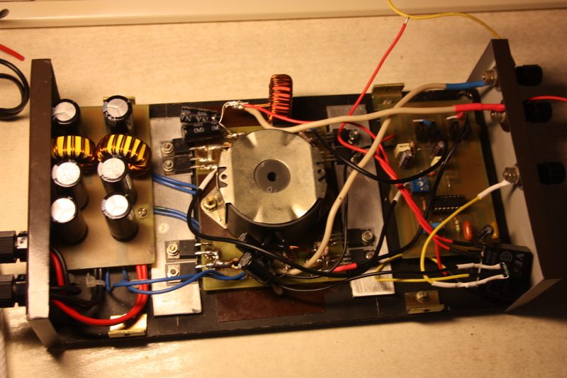
The input section contains the idle relay triggered by head unit "remote" signal and the PWM generator circuit on the PCB. The relay enables or disables the PWM circuit. This will turn the amplifier on or off.
The conversion section contains the transformer in the middle, a set of switching mosfets on one side and a set of rectifiers on the other side. Both mosfets and rectifiers are mounted onto the baseplate (5mm aluminium) though the aluminium bars. This ensures proper cooling. The mosfets are IRF3025 paralleled (with 110A per device current capability) and the rectifier diodes are MUR1560. During the testing I was not even able to make them warm.
The output section contains inductors and capacitors for smoothing the output voltage. The whole inverter circuit is encased in a separate metal casing to provide extra noise shielding for the other circuits around it. The output voltage for supplying the amplifier modules is about +/-32V.
Both the output and the conversion PCB contain large tracks on the bottom side that are heavily covered with solder to improve the current capacity.
The flaw
The flaw in the original ESP schematics is tying together "ground" circuits of the 12V side and the amplifier side. Once the amplifier is connected to the head unit, a ground loop is formed through the head unit chassis connection, signal cables and the amplifier (inverter) chassis connection.
In my case, I had a loud ignition switching noise coming through the amplifier. The noise would have made listening impossible. When revving up the engine it sounded like a loudly whistling turbo.
The solution is to untie the "ground" circuits. Almost all commercial car amplifiers do this. While looking for solutions I did not see any commercial car amp schematics that connected both grounds directly. There is coupling but it is always done through a 10k-47k resistor and 0.01uF-0.1uF capacitor in parallel between the grounds.
The voltage-regulating feedback loop has to be disconnected after untying the grounds. The schematics has to be modified to make it run at full PWM and to avoid interference from the disconnected feedback circuit. This was a bit inconvenient as I had to remove some turns from the switching transformer as the output voltage was a bit high without feedback.
Getting rid of the feedback loop has huge advantage of removing a potentially unstable component from the system. A feedback loop stability depends on the transformer leak inductance, output capacitor and inductor types and sizes and many other such hard-to-measure parameters. Unstable feedback loop is very hard to debug. It also makes the system less resistant for interference from EM fields of high switching currents.
The ignition noise completely disappeared from the amplifier. I still had small amount of noise from the amplifier cooling fan. The cooling fan was a typical PC fan. It produces rotating magnetic field and some of that field escapes from its motor. I solved the issue by moving the filtering/input section board and the wires away from the fan.
Amplifier modules
The amplifier modules were based on a simple class AB circuit. I have long lost the actual schematics but according to the components they are good up to +/-36V supply voltage. This gives about 120W of sine power into a 4 ohm load. I'm running them bridged which gives 480W of sine power into a 4 ohm load. When driven into a slight clipping, they would give a bit more. For normal listening this is enough power. The output devices are MJL21193/MJL21194 and mounted onto a fan cooled heatsink pair.
I first thought about using class D modules. That would have got rid of bulky heatsinks. However, I was not able to find any class D modules in the local electronics stores. There is lots of stuff on eBay but god knows how reliable they are. A car fire is the last thing I want. I have used an UCD module for a project previously but they require a bit higher voltage than my inverter was putting out.
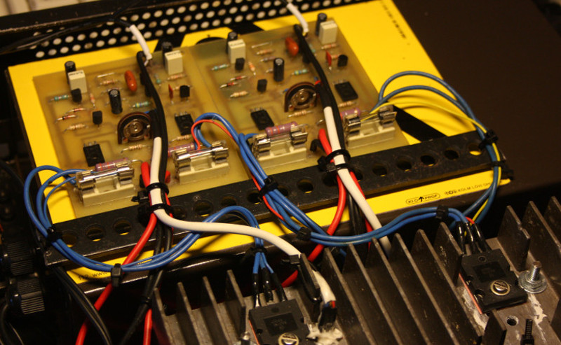
The amplifier module boards have individual fuses. The fuses are rated 6.3A which seems to be enough. The boards have no short-circuit protection and the fuses will prevent fire when the output gets shorted or the output devices blow up with short-circuit.
Input section
Besides the power inverter and the amplifier modules there is a small circuit to act as a low-pass filter and a bridge circuit. The bridge circuit inverts the signal for one channel so that its output is in the opposite phase with the other channel. A speaker is connected between the channels. Bridging doubles the output signal voltage and quad-doubles the power. I built the circuit on a solderable breadboard. I did start with a generic initial schematics but worked out the details of the circuit on-the-fly while soldering it.
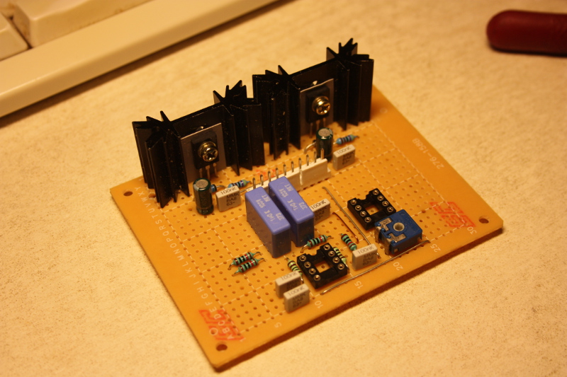
The circuit uses NE5532 opamps. I had some of them left over from old projects. The two power transistors mounted on the heatsinks work as linear voltage regulators to convert the power amplifier supply voltage (+/-32V) down to +/-12V which is suitable for the opamps. The circuit also contains a gain pot for matching the signal level to the head unit's signal level.
The detailed signal path:
- High-pass filters (about 12Hz, 6dB slope).
- Mixing buffer (1st half of 1st opamp, signal is turned into mono).
- Low-pass filter (200Hz? 12db slope, 2nd half of 1st opamp).
- Gain buffer (1st half of 2nd opamp).
- Phase inverter for one channel (2nd half of 2nd opamp).
Putting it all together
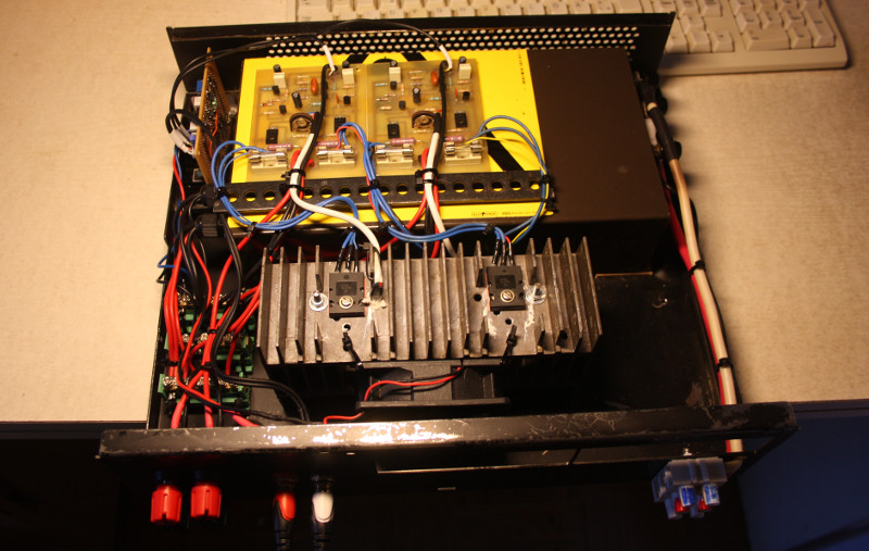
All parts of the amplifier were put into an old desktop PC case. It is smaller than normal ATX cases but still able to fit all the components. I tried to paint the case but the black spray did not stick well onto the polished surface. It does not bother me much. The upper cover is matte and the paint on it is much stronger.
The cooling fan works on the reduced voltage (near 7V) and through the idle relay. It cannot be connected directly to the 12V bus as it would drain the battery. The amplifier does not have overheating protection at the moment. I have planned to add it as an additional circuit through the idle relay so that it would turn off the power inverter once the heatsink temperature rises over the critical level.
The binding posts used for the output are Pomona 6883. They are rated for 30A and come for a very low price. The 12V power post is a screw terminal with steel leaf springs. It accepts 25mm^2 cable and the springs ensure that the connection does not come loose. The RCA signal connections are crap tho and I fear I have to replace them some time. They were advertised as "gold-plated" but still oxidate like crazy. It's possibly some fake stuff.
It took about 2 weeks to put together the amplifier. Most of the time was spent on testing and dealing with the ground loop issue.
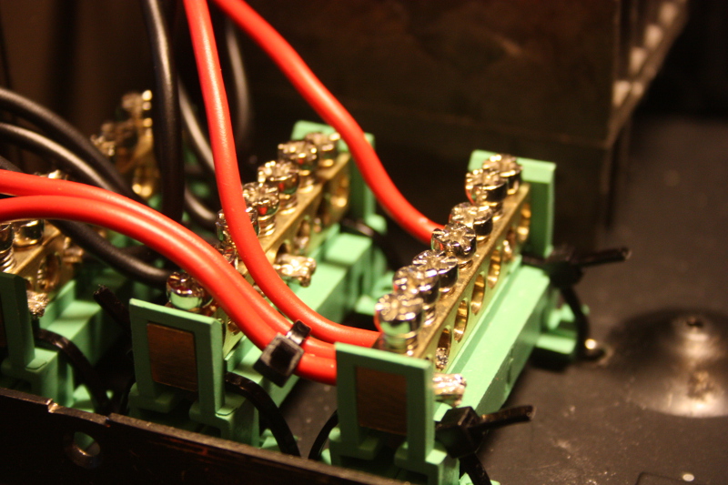
Unreliable screw connectors
The power from the inverter is distributed to the amplifier modules using the screw connectors. Unfortunately, these connectors turned out to be not reliable in practice. The screws would unscrew itself due to vibration. One channel started to periodically lose power due to this and the volume increase and decrease because of that after 2 weeks of the installation. I fixed this by gluing the screws into place.
Subwoofer
The subwoofer uses a 15" Hertz ES-380.5 as the speaker. I had an empty subwoofer box from another old project. The existing box almost matched the recommended box: it had to be cut smaller and required a new vent. I cut the box smaller and made the new vent from a plastic water tube. I also reinforced the corners. At the end the box was still a bit large and to obtain the target volume I used a volume filler cut from a styrofoam block and glued it inside the back wall.
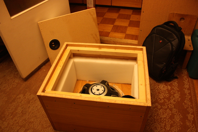
The inner side walls are damped with polyurethane, obtained from a local furniture store. The outer sides of the enclosure are covered with glued-on carpet. It took 2 days to build the box.
Installation
I finally installed the amplifier and the subwoofer into my Passat B5.5. It took one day to set up the power and signal wires. I routed the power wire through the driver side and the signal wire through the passenger side. There were some nice YouTube guides how to open the side panels (that can be tricky). One note: a 4.5m signal cable is a bit short for the station wagon type of a car body. I would recommend 5.5m. I use the Alpine UTE-72BT head unit. It comes with an USB support (I listen songs from an USB stick) and line/subwoofer outputs.
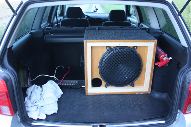
The power wires coming from the amplifier and going to the opened trunk side panel are now covered with black cloth tape. The side panel is mounted back too making the looks a lot better. So far the system has been proven to be quite reliable (minus the screw connector issues) and sounds pretty good.